Side-by-side hyper-realistic copper-core and graphite-core pans showing heat distribution; copper heats through thickness, graphite spreads heat across the surface.

Graphite vs. Copper Core: Which Has a Faster Heat Response?

When comparing graphite vs. copper cores, the question of which has a faster heat response depends entirely on the direction of heat flow and the specific thermal properties required for your application. Copper is an industry standard known for its high thermal conductivity (approximately 400 W/m·K) and isotropic nature, meaning it moves heat equally well in all directions. 
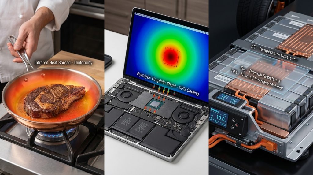
This makes copper cores the premier choice for high-performance cookware and heavy-duty electronics where heat must move quickly through the thickness of the material. However, modern engineering has introduced pyrolytic graphite, which boasts a significantly higher in-plane conductivity (up to 1500 W/m·K) while remaining incredibly lightweight. If your goal is rapid lateral spreading to eliminate hotspots in slim devices like smartphones or laptops, graphite often outperforms copper due to its superior thermal diffusivity.

Understanding the trade-offs between these two materials is essential for optimizing energy efficiency, safety, and performance. While copper offers a predictable and robust response for transferring heat across layers, graphite’s anisotropy—its tendency to conduct heat much faster across its surface than through its depth—requires a more strategic design approach. Choosing the right core involves weighing factors like thermal mass, contact resistance, and the specific geometry of your system. Whether you are a professional chef seeking the perfect sear or a hardware engineer managing CPU thermals, this guide provides a quantitative comparison of copper and graphite to help you determine which material offers the fastest, most effective heat response for your needs.

Why Heat Response Matters: Graphite vs. Copper Core

You’ll get a focused, comparative view of how graphite and copper cores behave when heat is applied. Understanding heat response — how quickly a material changes temperature and spreads heat — helps you judge performance, safety, and energy efficiency in cookware, electronics, and thermal systems.

This article covers basic thermal physics, a quantitative comparison of properties, the effects of construction and interfaces, trusted test methods, application outcomes, and a practical decision framework so you can choose the right core for your specific needs. It gives clear, actionable guidance with quantified trade-offs included.

1

Understanding Thermal Conductivity, Heat Capacity, and Diffusivity

Copper pan conducts heat vertically while a graphite sheet spreads heat laterally, with numeric labels for k, cp, ρ, and α, illustrating thermal diffusivity differences.
Copper transfers heat efficiently through thickness; graphite excels at lateral spreading. Material selection depends on application and geometry.

The three properties you must track

You need to think in terms of three physical properties, because together they determine how quickly a material’s temperature changes and how fast heat moves through it.

Thermal conductivity (k): how readily heat flows through the solid. Higher k means faster lateral spreading.
Specific heat capacity (cp): how much energy is required to raise 1 kg of material by 1 K. Higher cp increases the energy you must add to change temperature.
Density (ρ): mass per volume; it converts cp into thermal mass per unit volume.

These combine into thermal diffusivity, α = k / (ρ·cp), which directly controls the speed at which a temperature change propagates through a material. If α is large, a surface temperature step diffuses quickly into (or across) the material.

Why conductivity and thermal mass act differently

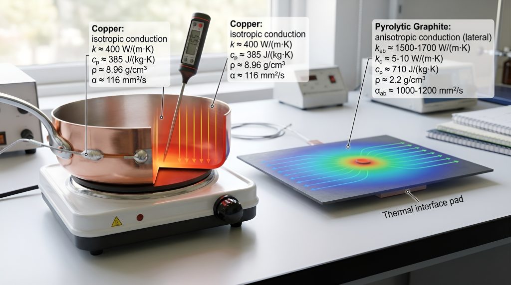
High k makes heat flow quickly across the material, which you feel as rapid lateral equalization (good for cookware bottoms or heat spreaders). Low ρ·cp reduces the total thermal mass that must be heated, so surface temperature rises faster for a given heat input. Practically, copper has very high k (~400 W/m·K) but also high ρ; graphite/carbon can have lower bulk k but much lower density and a higher cp, so the net α can be similar in some orientations.

Example product context:

All-Clad Copper Core pans exploit copper’s k to distribute heat quickly across the pan bottom.
3M / Fujipoly graphite sheets are used in electronics as thin, low-mass lateral heat spreaders—they rely on low mass and high in-plane conductivity.

Anisotropy and contact resistance — the real-world spoilers

Graphite is often highly anisotropic: its in-plane conductivity can be tens to hundreds of times greater than through-thickness conductivity. That makes it excellent for spreading heat laterally but poor at moving heat across a thickness. Copper is effectively isotropic, so its behavior is more predictable.

Contact resistance at interfaces (poor surface flatness, gaps, oxides) can dominate performance. To reduce it you should:

Clean mating surfaces and use a thin thermal interface material (paste, pad, solder).
Increase contact pressure or use conformal adhesives.
Prefer soldered or brazed joins for permanent, low-resistance connections.

Quick, actionable checks

Always ask for thermal diffusivity (α) or ρ·cp + k, not just k.
For fast through-thickness response, favor thin, high-k metals (copper).
For rapid lateral spreading with low added mass, consider graphite sheets or carbon composites, but verify through-thickness performance for your use case.
2

Material Properties: Quantitative Comparison of Copper and Graphite

Copper pan transfers heat vertically while a pyrolytic graphite sheet spreads heat laterally, with numeric labels for k, ρ, cp, and α, illustrating thermal diffusivity and anisotropy differences.
Copper excels at through-thickness heat transfer; in-plane graphite spreads lateral heat faster. Numerical properties guide material choice for performance-critical applications.

Representative physical values you can use

You’ll get faster intuition if you work with numbers. Typical, representative properties (order-of-magnitude, engineering values) are:

Copper (pure): k ≈ 385–400 W·m⁻¹·K⁻¹, ρ ≈ 8,960 kg·m⁻³, cp ≈ 380–390 J·kg⁻¹·K⁻¹.
Graphite (ordered/pyrolytic, in-plane): k ≈ 500–1500 W·m⁻¹·K⁻¹, ρ ≈ 1,800–2,200 kg·m⁻³, cp ≈ 700–800 J·kg⁻¹·K⁻¹.
Graphite (through-thickness / bulk): k ≈ 5–20 W·m⁻¹·K⁻¹ (much lower than in-plane).

These ranges explain why graphite can sometimes “beat” copper in spreading but lose badly when you need heat to cross thickness.

How to compute thermal diffusivity (and why it matters)

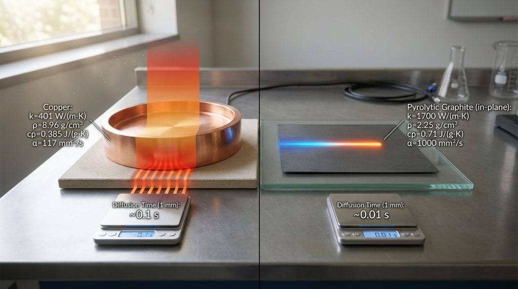
Thermal diffusivity α = k / (ρ·cp) controls how fast a temperature perturbation spreads through material. Workable examples:

Copper: α ≈ 390 / (8,960·385) ≈ 1.1×10⁻⁴ m²/s.
Pyrolytic graphite (in-plane): α ≈ 1,000 / (2,000·700) ≈ 7.1×10⁻⁴ m²/s.
Graphite (through-thickness): α ≈ 10 / (2,000·700) ≈ 7.1×10⁻⁶ m²/s.

Practical rule: diffusion time scales like t ≈ L²/α. For a 1 mm path (L = 0.001 m):

Copper: t ≈ 0.009 s (≈ 9 ms).
In-plane graphite: t ≈ 0.0014 s (≈ 1.4 ms).
Through-thickness graphite: t ≈ 0.14 s (≈ 140 ms).

So, in-plane graphite can diffuse lateral temperature changes an order of magnitude faster than copper for the same path length; graphite’s through-thickness response can be orders of magnitude slower.

Thermal effusivity — the “how it feels” metric

Effusivity e = sqrt(k·ρ·cp) measures how readily a material exchanges heat with another body (how “hot” a surface feels under a heat pulse). Using the representative numbers:

Copper e ≈ sqrt(390·3.45×10⁶) ≈ 3.7×10⁴ (SI units).
In-plane graphite e ≈ sqrt(1,000·1.4×10⁶) ≈ 3.7×10⁴.

Surprisingly, copper and highly ordered graphite can have similar effusivity, so an initial surface temperature jump can feel comparable even though the internal diffusion mechanisms differ.

Practical takeaways and product context

If you need fast through-thickness response (heating a pan bottom or a thermal via), prioritize high through-thickness α — copper or thin copper layers (All-Clad Copper Core pans) are reliable.
If you want ultra-fast lateral spreading with minimal added mass (thin heat spreaders in laptops, Thermal Grizzly Carbonaut or Fujipoly graphite sheets), use high in-plane graphite but check through-thickness limits.

Next, you’ll see how core construction, geometry, and interfaces amplify or negate these material advantages in real assemblies.

3

How Core Construction, Geometry and Interfaces Change Heat Response

Copper pan with bonded layers heats vertically while graphite sheet spreads heat laterally; interfaces, adhesives, and layer thickness visually annotated with thermal diffusion effects.
Construction, thickness, and interfaces dictate heat response: copper excels through thickness with metallurgical bonds; graphite spreads laterally but needs correct orientation and flat contact.

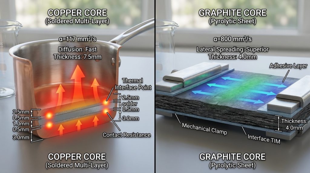
You’ve seen raw material numbers — now learn why a part’s construction often determines the real-world heat response. Small changes in thickness, layering, surface area and interfaces can flip who “wins” in a product.

Heat spreading vs. through-thickness transfer

Heat has two jobs: move laterally (spread) and move through thickness (transfer). Thin copper layers heat locally very fast because of high k and small thermal mass; they give rapid local temperature rise but limited lateral reach. Conversely, a thicker graphite spreader (high in-plane k) will equalize temperature across a surface faster — think laptop graphite sheets (Apple, Samsung) that take hotspots and smear them out.

Tip: if your failure mode is a hotspot (local power spike), prioritize in-plane spreading; if you must transfer heat across a thickness (cookware, heat pipes, vias), prioritize through-thickness α.

Geometry, thickness and surface area

Time constant scales like t ≈ L²/α. Doubling core thickness quadruples diffusion time. Adding fins or increasing surface area improves convective cooling but does nothing to intrinsic in-plane vs through-thickness tradeoffs.

Actionable step: for faster response, reduce the critical thermal path L (thin the layer), or increase α (choose higher-diffusivity material) in that direction.

Interfaces: bonding layers, TIMs and contact resistance

Interfaces often dominate. An adhesive layer, oxide film or an air gap can add orders of magnitude more resistance than the bulk. Examples:

Soldered/brazed copper stacks (All-Clad Copper Core cookware) have low interface resistance and long-term reliability.
Adhesive-bonded graphite sheets or mechanical clamps with phase-change TIM can work but require proper pressure and gap-filling.

Practical tip: eliminate air gaps, use properly applied TIM (thin, well-wetted), and prefer metallurgical bonds where reliability is critical.

Failure modes that slow and kill response

Delamination: adhesive breakdown creates thermal barriers and hotspots — common in cheap multi-ply cookware or glued laptop spreaders.
Oxidation/corrosion: copper oxide and contaminated surfaces raise contact resistance; protective plating or coatings help.
Mechanical deformation: bowing changes contact pressure and increases localized resistance.

Quick product notes: All-Clad Copper Core pans heat quickly and keep good through-thickness transfer because the copper is clamped and bonded; Thermal Grizzly Carbonaut / Fujipoly graphite pads excel as thin lateral spreaders but need flat surfaces and correct orientation.

Next, you’ll learn how to measure these behaviors reliably — what tests and metrics cut through marketing claims.

4

How Heat Response Is Measured: Tests, Protocols, and Metrics You Should Trust

Copper and graphite samples undergoing thermal tests: laser-flash, Hot Disk, and guarded hot plate setups; infrared thermography and embedded sensors visualize heat flow, rise time, and thermal resistance.
Measuring heat response requires validated transient and steady-state methods: laser-flash, Hot Disk, and guarded hot plates reveal diffusivity, thermal resistance, and uniformity across copper and graphite cores.

You’ll be guided through standard and practical measurement methods so you can interpret claims and run meaningful tests yourself. Below are the transient and steady-state lab techniques, application-focused tests, the metrics that matter, and the common pitfalls to avoid.

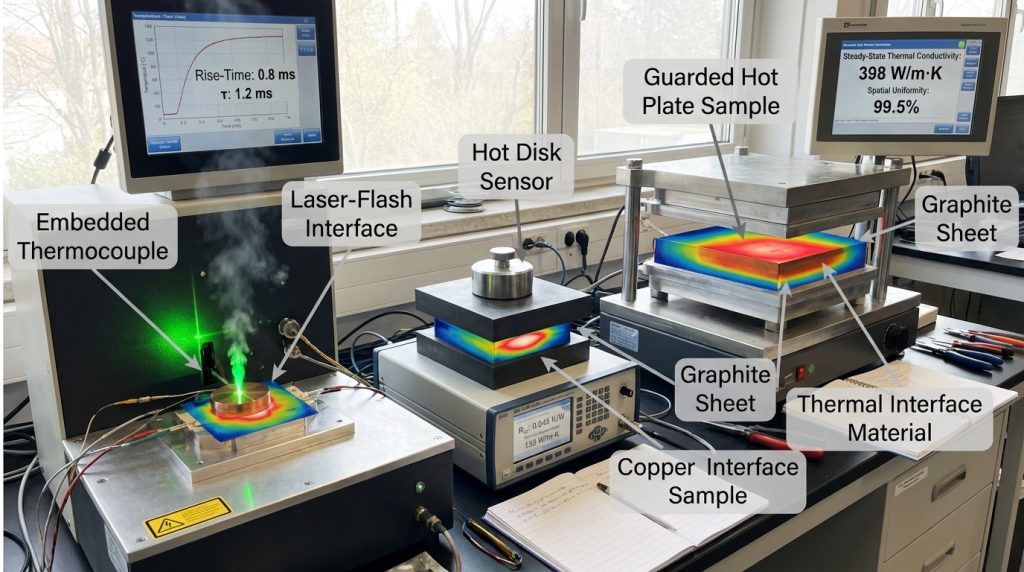
Transient techniques (diffusivity and short-time behavior)

Transient methods capture how quickly heat begins to move through a material.

Laser-flash (e.g., Netzsch LFA series): a short energy pulse heats one face; you measure the rear-face temperature rise and extract thermal diffusivity (α). Great for bulk samples and thin layers; fast and repeatable.
Transient Plane Source / Hot Disk (e.g., Hot Disk TPS 2500S): applies a heater/sensor disk between two sample halves and measures time-dependent response to get both k and α. Useful for anisotropic materials like graphite sheets.

How you use them: prepare flat, well-polished samples, control sample thickness, and run multiple shots to check repeatability.

Steady-state methods (thermal conductivity)

Steady-state tests measure k under constant heat flow.

Guarded hot plate (ASTM C177) and heat-flow meters give robust through-thickness k for bulk panels and cookware laminates.
For thin multilayers, combine steady-state with measured contact resistance to avoid misattributing interface losses to bulk material.

Application-oriented tests (real-world relevance)

These show operational performance you’ll feel or measure in the field.

Time-to-temperature rise: apply a known power (cartridge heater or electrical resistor) and log surface/embedded sensors (Type-K thermocouples or PT100). Record rise time to your target temperature.
Power vs. temperature curves: sweep input power and measure steady-state surface temperature to derive thermal resistance (°C/W).
Infrared thermography (FLIR E8/T540): visualize spatial uniformity and hotspots; complement point sensors.

Key metrics to trust

Time constant (τ): characterizes transient response (smaller = faster).
Rise time to target temperature: practical for cooktops and heatsinks.
Thermal resistance (Rth = ΔT/P): connects input power to temperature rise.
Spatial uniformity: temperature spread across the surface (important for cookware, displays).

Common pitfalls & best practices

Sample prep: avoid rough surfaces, unremoved adhesives, or oxidation.
Boundary conditions: clamp pressure, contact area, and ambient air change results — control them.
Sensor placement: embed sensors for through-thickness, use multiple surface sensors for uniformity.
Repeatability: run cycles, report mean ± std, and state measurement uncertainty.

Practical tip: if a vendor only quotes bulk k without specifying direction, thickness, or interface treatment, treat the number as incomplete — ask for test method, sample geometry and uncertainty.

5

Application-Level Performance: Cookware, Electronics, and Thermal Management Systems

Copper-core pan searing a steak, laptop with pyrolytic graphite heat spreader, and battery module with copper–graphite hybrid cold plates, each showing thermal distribution and practical heat response.
From kitchens to electronics and battery modules, application-level performance reveals how copper provides predictable through-thickness conduction while graphite spreads heat laterally with minimal mass. Hybrid stacks combine advantages for optimal thermal management.

You’ll find an application-focused comparison that translates material physics into practical outcomes. Below are clear, real-world takeaways so you can pick and specify the right core for your product or purchase.

Cookware: surface response, evenness, and retained heat

In the kitchen, you care about how fast a pan responds, how evenly it cooks, and how well it retains heat when ingredients are added.

Copper-core pans (e.g., All‑Clad Copper Core) heat laterally very fast, reducing hot spots and giving even searing across the surface. In a restaurant scenario, that means a steak browns uniformly the moment it hits the pan.
Graphite-based or very thin low-mass constructions heat quickly at the contact point and cool faster once removed—handy for lightweight camping pots or rapid temperature control, but they can show directional anisotropy (hot streaks) unless engineered into a multilayer.

Practical tips:

If you want quick, predictable surface response and evenness for high-heat cooking, prioritize copper-core cookware.
If weight and rapid on/off control matter (camping, portable induction), consider designs using low-mass or graphite-spread layers—test with an IR camera for uniformity.

Electronics and heat spreaders: spot cooling vs. area spreading

Your electronic hotspots are small and intense; your design constraints are weight and space.

Copper’s isotropic conduction makes it superior at pulling heat down from concentrated sources (CPUs, power transistors) and into fins or liquid loops—hence copper cold plates in high-performance PCs (Corsair/Noctua-style cooling solutions use copper bases or heat pipes).
Pyrolytic graphite sheets (PGS) excel as ultra-thin, lightweight spreaders inside laptops and phones, distributing heat laterally across a broad area without significant mass—Apple and other OEMs use graphite layers for this purpose.

How to choose:

For concentrated transient loads, choose copper or copper-clad interfaces.
For light, wide-area spreading and tight weight budgets, use graphite sheets with a thin copper interface at the sink.

High-power sinks, battery modules, and hybrid strategies

At high power, you’ll juggle thermal resistance, mass, manufacturability, and mechanical needs.

Battery packs and PV inverters often favor metal cold plates (copper or aluminum) for predictable, solderable interfaces and mechanical robustness.
Graphite reduces weight and can even out cell-to-cell temperature spread when laminated around modules.

Hybrid approaches you can implement:

Copper–graphite stacks: graphite for lateral spreading + copper inserts at attachment points.
Copper plating on graphite: makes the sheet solderable while preserving low weight.
Use compliant TIMs and controlled clamp pressure to minimize interface resistance.

Actionable checklist:

Map heat source size/intensity.
Prioritize spot conduction (copper) vs. area spreading (graphite).
Prototype hybrid stacks early and measure ΔT under realistic loads.

Next, you’ll use these application insights to build a practical decision framework for selecting the right core for your specific use case.

6

Choosing the Right Core: A Practical Decision Framework for Your Use Case

Decision framework for choosing copper, graphite, or hybrid cores, showing graphite for fast transient response, copper for steady-state heat removal, and hybrid stacks for combined performance.
A practical decision framework helps you pick the right core based on transient response, steady-state capacity, spatial uniformity, weight, and mechanical needs. Validation tests ensure your material choice meets real-world requirements.

Use this checklist and quick decision flow to pick graphite, copper, or a hybrid—and to design validation tests for your specific geometry and loading.

Rank priorities (quick flow)

Transient speed (how fast temperature changes): prefer graphite or low-mass constructions for contact-point response; copper if you need fast lateral collection from a point source.
Steady-state temperature and heat removal capacity: prefer copper.
Spatial uniformity across an area: prefer graphite for lateral spreading, or copper–graphite hybrids.
Weight constraints: prefer graphite.
Mechanical strength, solderability, and attachment robustness: prefer copper or copper-clad graphite.
Manufacturability and cost: aluminum/copper often cheaper/product-ready; graphite requires lamination/metallization.
Corrosion resistance: graphite > copper (unless plated); copper needs protective finishes.

Material recommendations + validation tests

If you prioritize transient surface response (e.g., camp stove pot, quick-response sensor): choose low-mass graphite or thin graphite layers. Test: step-power heating with IR thermography, record surface rise time (t10–90).
If you prioritize steady power removal (e.g., CPU cold plate, high‑power battery): choose copper base or copper inserts. Test: steady-state thermal resistance under applied heat flux and measured coolant delta-T.
If you need both spread and sink (laptop heat-spreading + heatsink): use graphite sheet + copper interface. Test: power-hold cycling, map hotspot ΔT with a thermocouple array and IR camera.
If mechanical joining or solderability is required: specify copper-plated graphite or copper inserts. Test: mechanical pull/torque, thermal cycling, and interface resistance under clamp loads.

Implementation notes (practical specs)

Thickness ranges: graphite sheets 0.05–0.5 mm (PGS); graphite laminates 0.2–2 mm; copper bases 0.5–3 mm for electronics; cookware cores 1.5–3.0 mm copper typical.
Surface finishes: mirror or brushed copper for cookware; nickel or copper plating on graphite for soldering; black oxide or chemically passivated finishes to reduce emissivity or oxidation where needed.
Bonding methods: diffusion bonding or vacuum brazing for copper–copper; metallization (Cu/Ni) + solder or adhesive for graphite-to-copper; compliant TIMs and controlled clamp torque to minimize interface resistance.
Maintenance: protect copper from corrosive cleaners, re-torque fasteners periodically, replace TIMs after thermal cycling, avoid prolonged oxidation temperatures for graphite (>400°C) unless protected.

With this framework you can narrow candidates, set targeted tests, and prototype hybrids quickly before final specification—next, the article wraps up with a concise summary of which core fits which need.

Summary: Which Core Gives Faster Heat Response for Your Needs?

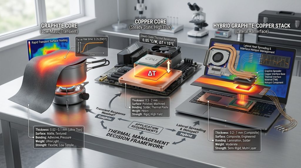
In most bulk, high-mass applications you’ll get faster transient heating and cooling with copper because its higher thermal diffusivity moves heat more quickly through the material. Graphite, however, can outperform copper when mass is low, heat spreading is directional, or weight and form-factor constraints dominate—especially in thin laminates, heat pipes, or anisotropic spreads.

Choose based on your priorities and geometry, then validate with representative transient tests under real boundary conditions. Use the decision framework and measurement guidance in this article to select and verify the best core for your application.

Leave a Comment

Your email address will not be published. Required fields are marked *