
The era of cluttered countertops and mismatched power bricks is officially over. As the world standardizes on USB-C, a new generation of smart kitchen gadgets is ditching traditional bulky plugs for sleek, universal power delivery. A USB-C hub is no longer just for your laptop; it’s becoming the central nervous system of the organized modern kitchen.
This post explores how to integrate USB-C power hubs into your kitchen layout to charge everything from cordless blenders to smart meat thermometers. We’ll show you how to eliminate “cord chaos” and create a high-tech, streamlined workspace that looks as good as it functions
Why a USB-C-Powered Smart Kitchen Matters
USB-C-Powered Devices for the Smart Kitchen
You’ll get a concise overview of why powering a smart kitchen with USB‑C is practical, efficient, and future‑forward. USB‑C brings uniform connectors, higher wattage, bidirectional power, and simpler installation that reduce clutter and increase flexibility. This article guides you to define use cases, set power budgets and success metrics, and understand USB‑C PD protocols and safety standards.
You’ll learn how to choose hubs, cables, converters, and appliances; design wiring topology and power distribution; and integrate smart devices, networking, and automation platforms. The final section shows how to implement, test, validate, and maintain your system. Expect data‑driven recommendations, clear safety checks, and interoperable design principles so your kitchen performs reliably and scales with future devices.
Follow along for practical, actionable steps.
Define Use Cases, Power Budgets, and Success Metrics
Map devices and interactions
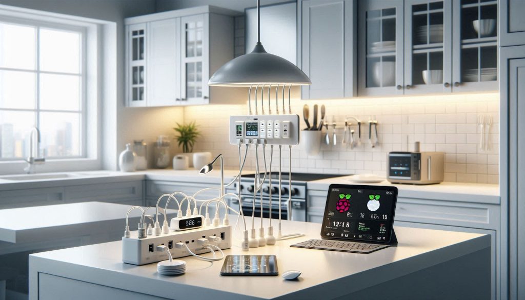
Start by listing every device and interaction in your kitchen: task lighting, under‑cabinet LEDs, fridge sensors, countertop displays, water pumps for instant hot water or coffee, peristaltic dosing pumps, voice assistants, Wi‑Fi mesh nodes, and a central automation hub (Raspberry Pi 4, Intel NUC, or a Home Assistant Blue). For each device note form factor (fixed or movable), data connectivity, and whether it must stay powered during outages.
Create a device inventory and empirical measurements
For each entry capture two power states: idle (background) and peak (boot, heating element, pump run). Wherever possible measure with tools: a USB‑C power meter (ChargerLAB Power‑Z), or for AC devices use a Kill‑A‑Watt. Example real‑world figures: Raspberry Pi 4 — idle ~2.5–3W, peak ~7–8W; a 7″ tablet display — idle ~3W, peak 10–15W; small peristaltic pump via a DC converter — peak 5–12W; smart camera — 2–4W.
Build the aggregated power budget
Sum peak draws for likely simultaneous events (e.g., brew cycle + display + lighting). Always add a safety headroom factor — 25–30% is typical for mixed loads; use 50% if you expect frequent surges or long cable runs. Convert totals into PD channel requirements: number of 5–20V rails, max wattage per port, and total wattage from the supply.
Define measurable success metrics
Choose clear targets you can test:
Document constraints that drive design
Record port counts, cable lengths, ingress/wet‑zone ratings, countertop clearance, and budget. Note vendor limits (some USB‑C chargers limit sustained power) and the need for certified cables (USB‑IF 100W) and PD negotiators.
Next, you’ll use this inventory and budget to select appropriate USB‑C PD profiles, chargers, and protective circuitry — the focus of the following section.
Understand USB-C Power Delivery, Protocols, and Safety Standards
You’ll need a crisp technical foundation so your kitchen’s PD ecosystem behaves predictably. This section gives the practical essentials—what’s negotiated, what matters for compatibility, and how to keep things safe.
How PD negotiation works (high level)
USB-C uses the CC (Configuration Channel) pins to advertise and request power. A source offers Power Data Objects (PDOs); a sink requests via a Request Data Object (RDO). If negotiation fails, devices fall back to default 5 V. Key takeaway: voltage and current aren’t free—your device will only see higher rails (9/15/20 V) after a successful PD handshake.
PD modes: fixed, variable, and PPS
Choose supplies that publish supported PDOs and list sustained power; some consumer chargers advertise 100 W but throttle after thermal limits.
Protocol details and real‑world effects
PD messages are BMC‑encoded on CC and include role swap, contract extensions, and alerts. In practice, mismatches cause stalls: a display may boot at 5 V and later jump to 20 V, causing brief brownouts if the hub isn’t sized for the inrush.
Safety protections and standards
Design and spec for:
Interpreting datasheets and measuring behavior
Check max Vbus, sustained wattage, thermal derating, and supported PDOs. Validate with:
Next, you’ll apply these requirements when selecting hubs, cables, converters, and appliances so negotiated contracts and safety margins align with real hardware.
Choose Hardware: Hubs, Cables, Converters, and Appliances
You now translate budgets and PD requirements into concrete parts. This checklist-driven section helps you pick hubs, power supplies, cables, PD controllers, and appliances that behave predictably in a kitchen environment.
Quick selection checklist
Hubs and power supplies: form-factor tradeoffs
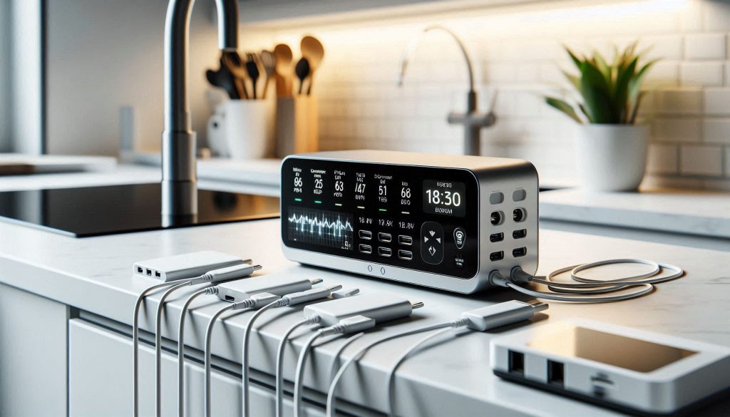
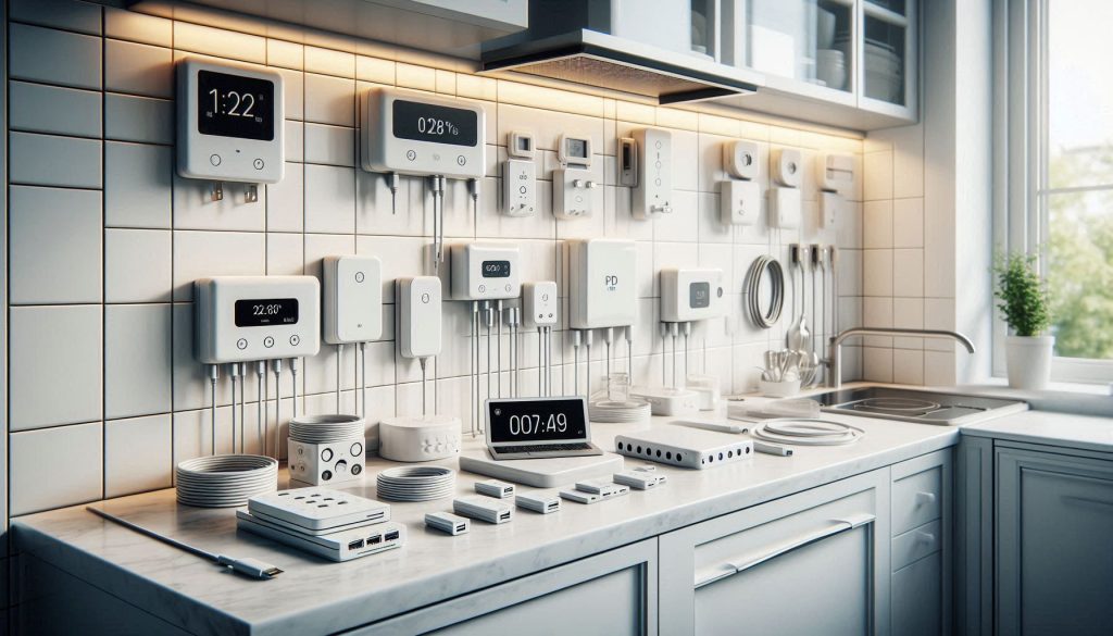
If you want centralized management, an in‑cabinet AC→DC enclosure (Mean Well-class industrial supplies) gives clean wiring and higher continuous power; it can deliver multiple USB-C PD ports via a PD-enabled hub (Anker/Satechi examples). Distributed wall‑mounted or under‑cabinet chargers (GaN bricks like Anker 737/65W or Satechi 108W hubs) reduce high-current trunking but increase the number of AC outlets and potential clutter. In kitchens, choose the option that minimizes heat inside cabinetry and keeps high-voltage AC away from wet zones.
Cables and converters: efficiency and thermal behavior
Embedded controllers and IoT modules
For custom appliances, use proven PD controller ICs or breakout boards (STMicro STUSB4500, Infineon/Cypress CCGx family, TI TPS65987D) or vendor breakout modules from Adafruit/Seeed to handle PD state machine and safety. For off‑the‑shelf IoT gear, favor devices that are USB‑C native (smart displays, LED drivers, networked cameras) or ones easily adapted with inline PD sink modules.
Vendor evaluation tips
Next, you’ll use these hardware decisions to draft wiring topologies and distribution zones so negotiated power contracts and safety margins map cleanly to physical runs.
Design Power Distribution and Wiring Topology for the Kitchen
You’ll translate component choices into a physical topology that minimizes voltage drop, meets code, and keeps water and heat risks separated.
Locate feeders, hubs, and zones
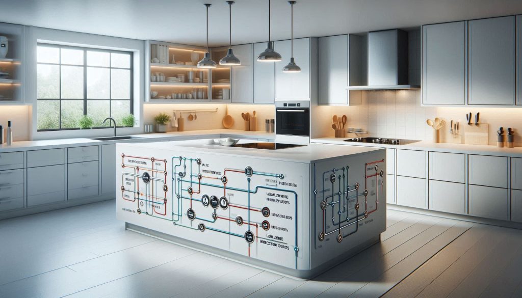
Place AC feed(s) and main PD hub(s) near appliance clusters: countertop zone, under‑sink zone (avoid inside sink cabinet), and pantry/media zone. For example, a central DIN‑rail Mean Well PSU in a ventilated cabinet feeding local Satechi/Anker PD hubs reduces long high‑current runs. Treat induction cooktops, built‑in ovens, and high‑power air fryers as separate high‑power zones with isolated feeders.
Calculate wire gauge and voltage drop (practical method)
Use this simple workflow:
Placement and selective isolation
Keep PD hubs close to loads to shorten DC runs. For high‑power devices use:
Grounding, redundancy, and EMI
Wet‑environment routing and inspection readiness
Use IP‑rated enclosures (Hammond/Bud), GFCI‑protected circuits, fire‑retardant cable grommets, and silicone seals for through‑cabinet penetrations. Document single‑line diagrams, PD negotiation tables, component datasheets, load calculations, and label terminals and cables for inspections and maintenance.
Next, you’ll connect these physical decisions to device-level integration — mapping networking, automation controllers, and orchestration so negotiated PD contracts translate to reliable, automated behavior.
Integrate Smart Devices, Networking, and Automation Platforms
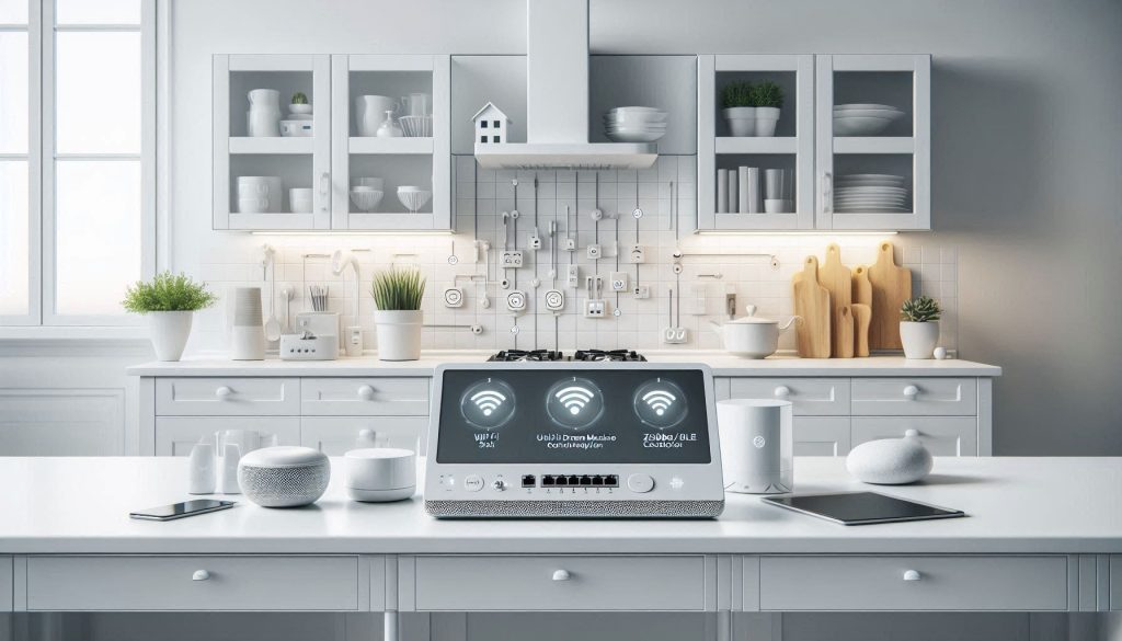
Network architecture choices
You’ll want a wired Ethernet backbone for reliability and VLAN-capable Wi‑Fi for convenience. Typical practical stack:
This hybrid minimizes wireless congestion and keeps critical traffic on wire.
Secure device onboarding and segmentation
Onboard every device with a documented process: unique credentials, certificates where possible, and VLAN assignment by role (sensors, appliances, media, guest). Use:
Choosing an automation platform or hub
Pick a platform that supports local APIs and common protocols: Home Assistant for extensibility and local control; Hubitat for low‑latency local automations; HomeKit if you’re deep in Apple’s ecosystem. Combine with Node‑RED for orchestration and MQTT for a common message bus.
Prioritize low‑latency controls
For safety-critical actions (gas shutoff, motorized vent, induction cutoff), keep logic local and target latencies:
Example: a smoke trigger should run a local automation in Hubitat/Home Assistant to trip a relay (Shelly 1/1PM or DIN relay) without cloud dependence.
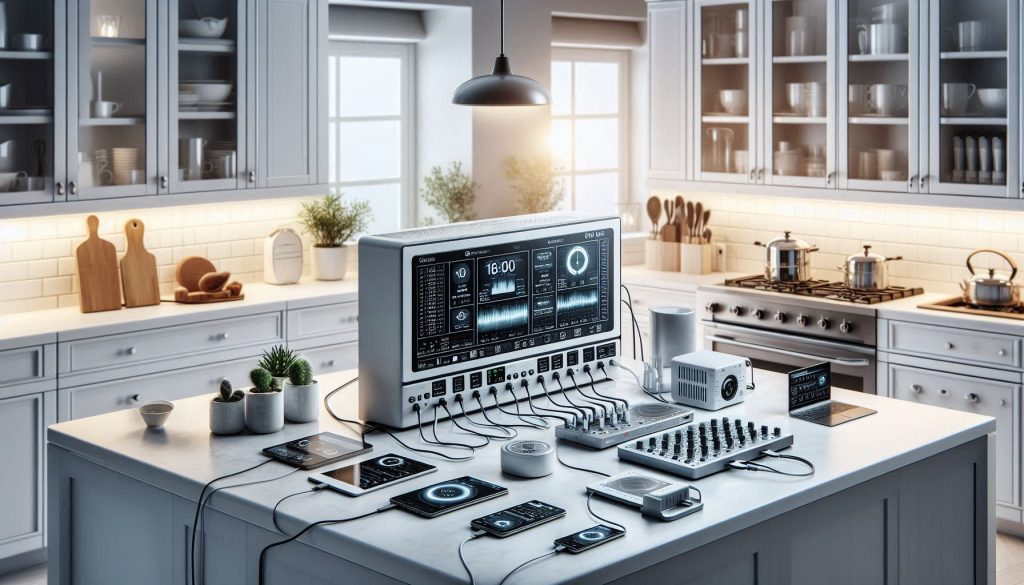
Telemetry, logging, and analytics
Plan bandwidth and storage; rough device figures:
Centralize logs and metrics: InfluxDB + Grafana for time series, Prometheus for system metrics, and a syslog/MQTT archive. Retain high‑resolution telemetry for 7–30 days, aggregated rollups for long term. Add alerting (email/SMS/webhook) for anomalies.
By designing your network, onboarding, and automation with these constraints, you turn discrete USB‑C devices into a cohesive, secure, and responsive smart kitchen ready for iterative improvement.
Implement, Test, Validate, and Maintain Your System
Staged implementation plan
Roll out in predictable stages: bench prototyping → pilot zone (one countertop/zone) → full kitchen. On the bench, validate adapters, hub firmware, and PD negotiation before you touch cabinetry. In one real project, a bench test caught a hub that refused 45W PPS requests — avoiding field rewiring and a weekend of downtime.
Bench testing checklist
In-situ commissioning checklist
Automated test harness
Build scripts (Python + pyusb/libusb or vendor SDKs) to:
Acceptance criteria examples
Firmware, keys, and incident procedures
Maintenance plan & monitoring
These steps get your deployment reliable and auditable; next, we’ll pull everything together into practical next steps.
Bringing It Together: Practical Next Steps
Finalize your device inventory and power budget, then procure certified USB-C power components that match those specifications. Follow the wiring and safety checklist, use PD-compliant hubs and cables, and plan redundancy for critical loads. Adopt modular testing and monitoring: validate each circuit empirically, log results, and adjust thresholds based on real measurements.
Prioritize safety compliance, clear documentation, and maintainable diagrams so troubleshooting is straightforward. With regular validation and firmware updates your USB-C-powered smart kitchen will perform reliably and safely. Start small, iterate, and scale only after measured success. Take action now with measured confidence.