
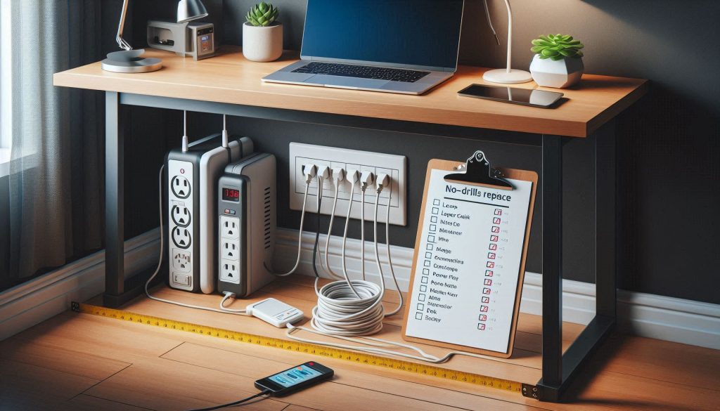
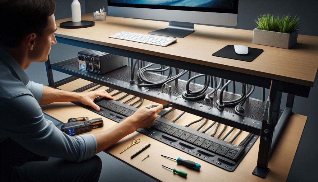
Tangled wires and bulky power strips can quickly turn a premium workspace into a cluttered eyesore. Finding an effective under-desk cable management solution is essential for anyone looking to achieve a clean, minimalist aesthetic without the permanent damage of drilling into expensive furniture. Whether you are a remote professional or a dedicated gamer, a no-drill under-desk cable tray provides the perfect balance of stability and flexibility. By keeping your cords off the floor and tucked neatly out of sight, these non-invasive organizers maintain the integrity of your standing desk while instantly elevating your office’s professional look.
Investing in a dedicated power strip organizer does more than just improve your room’s appearance; it significantly enhances your overall productivity and safety. Research suggests that physical clutter can lead to a loss of focus, yet a streamlined desk wire organization system ensures your workflow remains uninterrupted by reducing dust buildup and preventing accidental disconnections. By utilizing damage-free mounting methods like heavy-duty C-clamps or adhesive tracks, you can protect your equipment and keep your warranties intact. This guide explores how to choose and install a secure, reversible system that keeps your home office streamlined, organized, and trip-hazard free.
Say Goodbye to Cable Chaos
Tangled wires and bulky power strips can quickly turn a premium workspace into a cluttered eyesore. Finding an effective under desk cable management solution is essential for anyone looking to achieve a clean, minimalist aesthetic without the permanent damage of drilling into their furniture. Whether you are a remote professional or a dedicated gamer, a no-drill under desk cable tray provides the perfect balance of stability and flexibility, keeping your cords off the floor and tucked neatly out of sight.
Investing in a dedicated power strip organizer does more than just improve your room’s appearance; it enhances your overall productivity and safety. By elevating your power bricks and cables, you reduce dust buildup and prevent accidental trips or disconnections during the workday. This guide explores how to optimize your desk wire organization using damage-free methods, ensuring your standing desk or home office remains streamlined, organized, and professional.
Why a No-Drill Under-Desk Cable Management Solution Matters
You lose up to 40% of work minutes to small interruptions from clutter and cable snarls. A no-drill under-desk organizer keeps cords off the floor and your workflow uninterrupted.
You need a tidy, safe workspace that does not damage your desk or void warranties. A non-invasive solution delivers improved ergonomics, fewer trip hazards, lower fire risk, and easier maintenance. Focus on measurable criteria: load capacity, surface compatibility, ventilation, and service access.
This article shows practical steps and decision rules so you can choose and install a secure, reversible system. You will learn how to estimate loads, compare mounting options, design cable routes, install without drilling, and maintain the setup. Use these data-driven guidelines to protect your equipment, your furniture, and your productivity.
These choices reduce downtime, simplify repairs, and keep warranty intact—making them smart investments for home and office environments everywhere else.
Assess Your Under-Desk Needs: Inventory, Loads, and Constraints
Get precise before you buy. A short, objective survey of what lives under your desk will keep you safe, compliant with warranties, and using the right no‑drill hardware.
Inventory devices and measure electrical load
List every device that will plug into the strip (laptop adapter, monitor, lamp, printer, phone charger, speakers, docking station). For each item record:
Tools and examples:
Quick example: laptop 65 W + monitor 30 W + speakers 10 W + lamp 40 W = 145 W steady (~1.2 A at 120 V). Add 20–30% headroom for peaks and charging surges.
Measure physical mounting and clearance
Measure desk thickness, underside materials, and the distance from the rear edge to legs or cable passthroughs. Note:
Useful tools: tape measure, calipers for tight spaces, and a flashlight for visual checks.
Cable types, plug orientation, and access needs
Differentiate power cables from low-voltage data (Ethernet, HDMI, USB). Keep high‑voltage and low‑voltage runs separated where possible.
Constraints and risk factors
Identify any hard limits before selecting a no‑drill option:
Imagine a remote worker who measured everything first and avoided a burned-out surge protector and an angry landlord. With this data-driven requirements list in hand, you’re ready to compare no‑drill mounting methods and pick hardware that matches your measured needs.
Compare No-Drill Mounting Methods and Hardware Options
You’ve measured and listed requirements — now match those requirements to mounting strategies. Below are the common no‑drill options, each evaluated for mechanical behavior, surface prep, environmental limits, and real‑world trade‑offs.
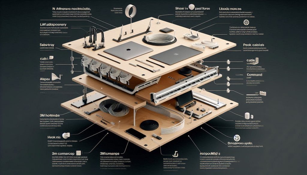
Adhesive-backed trays and hook mounts
Adhesive trays (foam‑tape backed or double‑sided VHB-style) and 3M Command-style hooks are fast and tidy.
Product highlights: 3M Command Large Clips (temporary) and 3M VHB 5952 (industrial bonding — check datasheet).
Clamp-style under-desk trays that grip the edge
Edge clamps or C‑clamp trays mechanically hold without adhesives.
Example: “C‑clamp” under‑desk trays available with PVC‑lined jaws for veneer protection — verify min/max thickness spec.
Removable adhesive anchors for zip ties/Velcro
Small puck anchors let you loop zip ties without trays.
Magnetic mounts (for ferrous under‑surfaces)
When your underside is steel, magnets are elegant.
Low-profile compression/bracket clamps
Compression brackets squeeze between desktop and underside without drilling or external lip.
When choosing, favor hardware with documented load ratings or UL/ETL‑listed power fittings. In the next section you’ll apply these choices to lay out strips and routes that meet your measured needs.
Design an Efficient Layout for Power Strips and Cable Routing
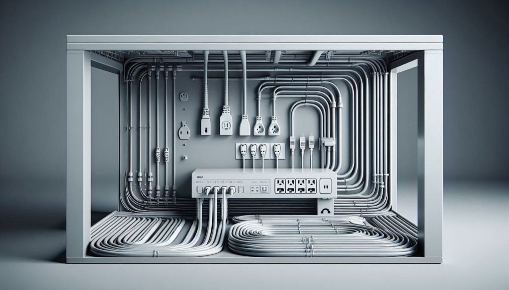
Translate your inventory and chosen mounting method into a physical plan that balances accessibility, cooling, and signal integrity. The goal: shortest safe mains runs, clear access to surge switches, separated power/data paths, and tidy serviceability.
Map the power-strip location first
Place the strip where cord lengths and voltage drop are minimized, switches are visible, and you can reach it without crawling under the desk.
Segregate power and data lines
EMI from high-current AC runs can corrupt sensitive signals. Separate and cross at right angles when necessary.
Plan cable paths, bends, and service loops
Respect bend radii and allow movement without re-routing.
Ventilation and heat management
Surge protectors and power bricks get warm—design clearances.
Validate with simple diagrams and measurements
Draw one-line diagrams and check lengths before you buy parts.
Step-by-Step Installation Using No-Drill Techniques
Follow a reproducible, safety-focused sequence so you get reliable results every time. Below is a practical, hands-on workflow that builds on your layout plan and keeps safety at the center.
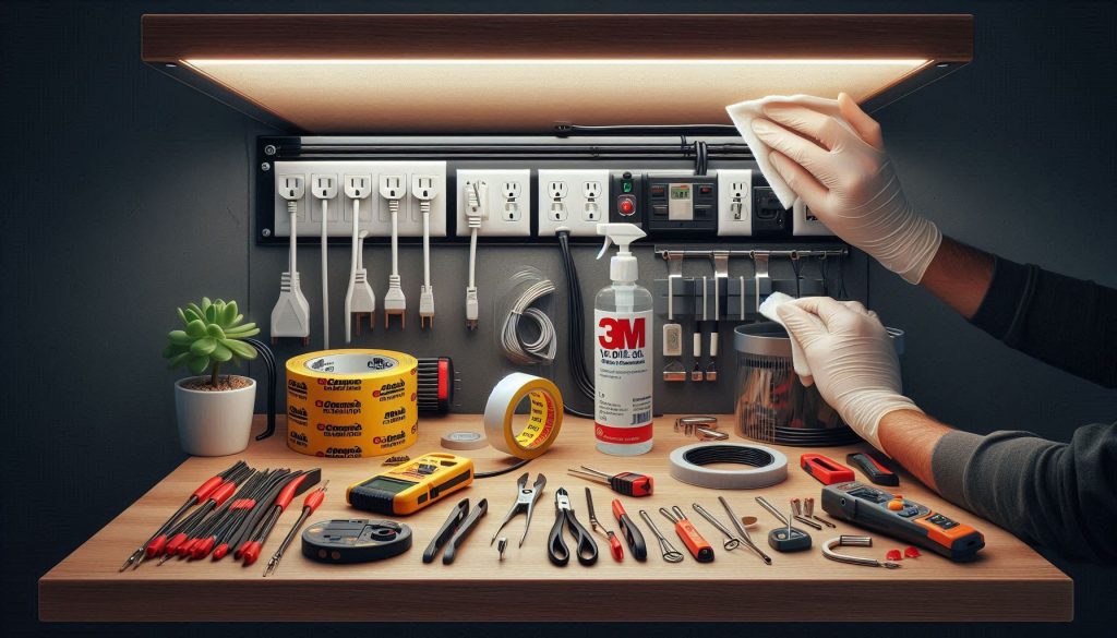
Preparation: clean, gather, and verify
Wipe the underside of the desk with isopropyl alcohol to remove grease and dust; adhesives bond poorly to contaminants. Gather:
Dry placement and mock-up
Position the strip and trays without adhesive. Check switch visibility, cord reach, and that you’re not blocking egress or drawer movement. This “dry fit” prevents surprises.
Apply adhesive anchors or engage clamps
Follow manufacturer instructions exactly:
Secure the power strip
Mount the strip to the anchors with supplied brackets or Velcro straps. For heavy strips, pair adhesive with a clamp to share load. Use low-profile brackets (Mockett-style) or heavy-duty Velcro wrapping around the body for vibration damping.
Route and label cables
Run power and data paths per your plan. Use:
Implement strain relief
Anchor each heavy cord within 2–4 inches of where it enters the strip using a clamp or adhesive anchor so the plug doesn’t pull on connections. For monitor PSUs, use a cable loop secured to the frame.
Validate electrically and thermally
Contingencies and safety checkpoints
If adhesives slump or fail, switch to clamp mounts or combine adhesive with mechanical clamps. If clamps aren’t available, reroute weight to a frame member and use zip ties around that member. Never overload circuits—sum the watts of attached devices and compare to breaker rating; distribute loads across wall circuits if needed.
Proceed next to maintenance and troubleshooting to keep this installation dependable over time.
Maintenance, Troubleshooting, and Future Upgrades
Keeping a no‑drill under‑desk system reliable means recurring checks, quick diagnostics, and a plan for incremental upgrades. Below are focused, actionable practices you can implement now.
Create a simple maintenance schedule
A real example: one office found adhesive creep after heavy summer heat; a monthly glance caught the softening before a strip detached.
Routine diagnostics and the right tools
Use these tests after major reconfigurations and any time you smell heat or see discoloration.
Troubleshoot common failure modes
A quick anecdote: relocating a laptop power brick from beneath a shelf to a vented spot reduced its IR reading by 12°C.
Planned upgrades and scaling
Document changes and labeling
With these routines and tools, you’ll detect issues early and scale confidently. Proceed to the Final Checklist and Risk‑Minimizing Practices to close out your project.
Final Checklist and Risk-Minimizing Practices
You now have a clear approach to deploy a no-drill under-desk cable management and power strip organizer that balances safety, accessibility, and furniture preservation. Follow the assessment, selection, layout, installation, and maintenance steps to minimize risk and maximize uptime. Keep load calculations current, monitor thermal performance after installation, and prefer certified components.
Schedule inspections, document your layout and circuit assignments, and replace suspect cables or adhesive mounts. If loads or usage change, reassess and upgrade components. Standardize parts, label runs, keep records to preserve safety and functionality without altering the desk. Proactively avoid downtime now.