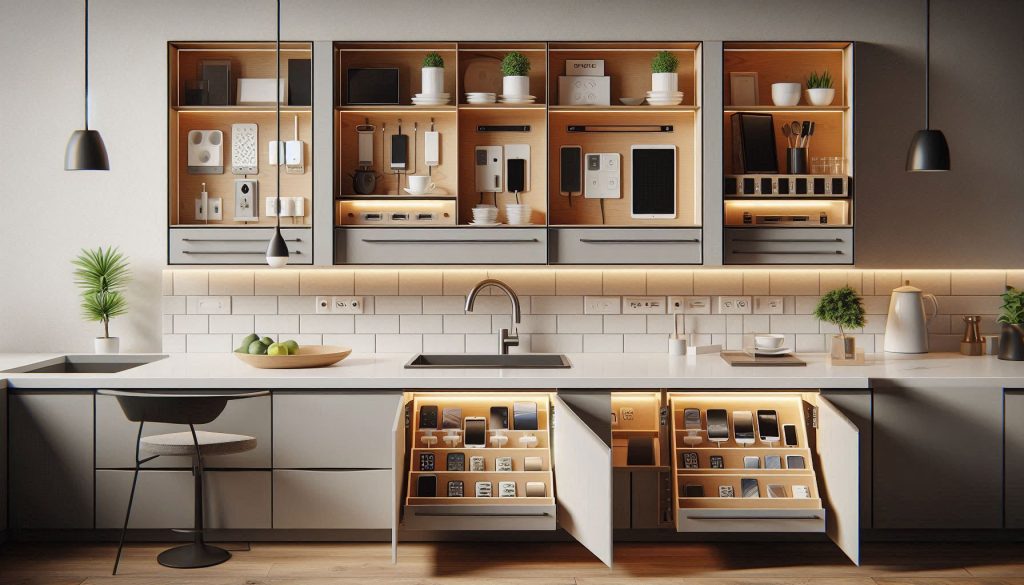
Tired of seeing a tangled web of USB cables and bulky power bricks cluttering your beautiful quartz or granite countertops? A hidden kitchen counter charging station is the ultimate solution for modern homeowners who need to power multiple devices—like iPhones, tablets, and laptops—without sacrificing aesthetics or workspace. Beyond just hiding the mess, a well-designed built-in charging hub centralizes your electronics, reduces trip hazards, and protects your expensive gadgets from kitchen spills. Whether you are looking for an in-drawer charging outlet or a sleek pop-up power strip, streamlining your tech integration is the key to a truly functional, minimalist kitchen.
In this comprehensive guide, we provide a data-driven approach to DIY and professional installation of concealed kitchen electronics docks. You will learn how to calculate your household’s total power budget, choose high-wattage USB-C PD (Power Delivery) components for fast charging, and ensure maximum electrical safety with proper ventilation and GFCI protection. From measuring cabinet clearances to selecting fire-resistant materials, this article covers everything you need to know to build a scalable, low-visibility charging solution that keeps your devices ready and your counters clear.
Why a Hidden Countertop Charging Station Makes Sense for Your Kitchen
You rely on multiple devices in the kitchen every day — phones, tablets, speakers, and sometimes laptops. Visible cords and bulky chargers create clutter, trip hazards, and distracted cooking.
A hidden countertop charging station reduces clutter and centralizes power management. It improves device safety by organizing charging currents and reducing cable wear. It also makes using devices more ergonomic and keeps counters clean for food prep.
This article gives you a practical, data-driven guide. You will learn how to assess needs, choose components, install safely, and maintain a station that fits your devices and habits.
Follow practical measurements, safety checks, and scalable designs to match current and future gadget loads.
1
Assessing Your Needs: Inventory, Power Budget, and Use Patterns
Before you pick hardware or cut holes in cabinetry, quantify exactly what you charge and how you use those devices.
Inventory your devices and power needs to design a perfectly sized and efficient hidden kitchen charging station.
This phase prevents expensive overbuilds or undersized chargers and helps match capacity to daily habits.
Step 1 — Make a device inventory
List every device that will regularly use the station and note typical charging power and connector type.
Phones (count) — phones typically draw ~5–25 W; newer iPhones with MagSafe can take ~15–20 W; many Androids accept 18–30 W or more with USB‑PD.
Tablets (count) — usually ~18–45 W.
Laptops (count) — commonly 45–100+ W (check your laptop’s charger).
Wearables and buds (count) — 2–10 W each.
Other electronics — speakers, cameras, e-readers, battery packs.
Example: 4 phones, 1 tablet, 1 laptop, 2 earbuds.
Write connector types next to each item (USB‑C PD, Lightning, MagSafe, USB‑A).
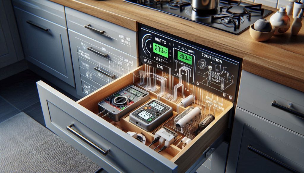
Step 2 — Convert to a realistic power budget
Add the maximum expected wattage for each device to estimate peak load; then factor in typical use (not all devices will draw max simultaneously).
Example calculation: 4 phones @ 15 W = 60 W; 1 tablet @ 30 W = 30 W; laptop @ 65 W = 65 W; 2 earbuds @ 5 W = 10 W → peak 165 W.
To convert to amperage on a 120 V circuit: amps = watts ÷ 120 → 165 W ÷ 120 ≈ 1.4 A (well below a 15–20 A circuit), but remember the kitchen counter is often on a shared 20 A circuit with appliances.
Tip: plan for 20–30% headroom above your estimated peak to accommodate inefficiencies and future devices.
Step 3 — Decide on fast‑charging support
If you rely on quick top‑ups or charging laptops from the station, include USB Power Delivery (PD) or Quick Charge in your spec. Multiport GaN chargers (Anker, Aukey, Satechi lines) offer PD outputs up to 100–120 W and dynamic power sharing—look for models with at least one high‑watt USB‑C PD port for laptops.
Step 4 — Measure space and map behaviors
Measure available counter or cabinet depth, drawer clearance, and ventilation space. Consider hidden locations:
Under‑counter shallow drawer (needs ventilation and cable pass‑through).
Built‑in pop‑up box on the island (works well for occasional visibility).
Behind a false backsplash with grommeted cables (very low visibility).
Observe where devices naturally sit during meal prep, whether cords can reach without draping across prep areas, and if users prefer devices visible or hidden. Note peak times (evenings? mornings?) to refine concurrent charging scenarios.
This inventory and behavior mapping gives you the numerical and physical constraints you need to choose hardware and layout—next, you’ll translate that data into concrete design choices and component selection.
2
Design Options and Components: Choosing the Right Hardware
With your needs mapped, choose a form factor and hardware that match power, space, and style.
Compare form factors and select the right hardware for a safe, efficient, and stylish hidden countertop charging station.
Below are proven layouts, the charging tech you should favor, and precise component criteria so you pick gear that’s safe, measurable, and future‑proof.
Common form factors and tradeoffs
In-drawer charging tray — Very low visibility; needs active ventilation or perforated tray; best for overnight charging but avoid high‑watt laptop charging in fully closed drawers.
Flip-up pop-up module (island or backsplash) — Easy access, good airflow when popped up, visible when in use; ideal if you want occasional concealment without a drawer.
Pull-out brick with vertical dividers — Excellent for staging multiple phones/tablets upright (prevents scratching); moderate ventilation; good for families who dock devices while prepping.
Hidden wall‑mounted box behind a false backsplash — Minimal countertop clutter, easy to hard‑wire, but plan larger access panel for servicing and heat dissipation.
Choose the form that matches how often you access devices and how much ventilation you can provide.
Charging technologies to adopt
Multi-port USB‑C PD hubs for laptops and tablets (look for 60–100 W total for a small family; larger households may need 120–200 W).
Dedicated Qi wireless pads for compatible phones and earbuds—use only with drawer designs rated for wireless use and with airflow.
USB‑A ports for legacy devices and accessories.
AC outlets (surge‑protected) for laptops, chargers with brick-style PSUs, or small appliances.
Example: a 100 W 4‑port GaN PD hub can simultaneously run a 65 W laptop + two 15 W phones and still leave headroom.
Component specs and safety priorities
Before buying, require these minimums:
Combined PD wattage matching your power budget (60–100 W for typical families).
Per‑port current limits approx. 3 A for USB‑C (verify at both 5 V and higher PD voltages).
Intelligent port negotiation (USB PD 3.0, PPS) and predictable power‑sharing (independent channel distribution preferred over opaque dynamic throttling).
Overcurrent and short‑circuit protection; thermal throttling and auto shutoff.
Surge protection and UL/ETL/CE listings; FCC compliance for wireless transmitters.
Physical hardware and installation components
Surge‑protected strips or hardwired outlet modules (brands: Tripp Lite, APC).
Inline fuses/circuit breakers or a dedicated GFCI-protected outlet for wet‑zone safety.
Power conditioning / UPS for sensitive devices (APC Back‑UPS, CyberPower).
Cable-management inserts, grommets, rubberized dividers, and silicone pads to prevent scratching.
Enclosure materials rated for fire resistance (look for UL94‑V0 or equivalent).
Vendor selection and verification
Prefer known manufacturers with clear spec sheets (Anker, Satechi, Belkin, APC).
Verify claims with a USB-C power meter or kill‑a‑watt-style load meter rather than marketing copy.
Insist on certificates and ask for measured distribution charts when buying high‑density hubs.
Next, you’ll translate these choices into a step‑by‑step installation plan—measuring cutouts, routing cables, and testing electrical safety.
3
Step-by-Step Installation: From Measurement to Final Testing
This step‑by‑step workflow is written so you minimize rework and risk.
Follow precise measurements and template testing to ensure a safe, accurate installation of your hidden charging station.
Move deliberately: measure twice, cut once, and verify electrical capacity before you power anything.
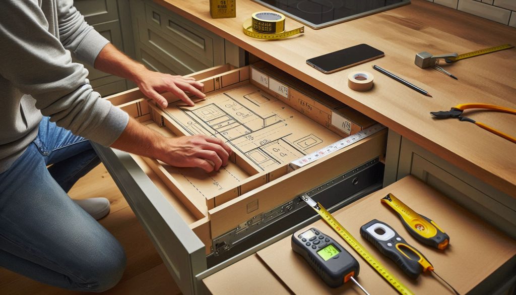
Measure, mark, and create templates
Record device footprints, cable exits, and hinge/drawer‑slide clearances on paper or with masking tape on the cabinet face.
Transfer dimensions to a cardboard template; test‑fit the template inside the drawer or on the counter to confirm clearance with hinges and slides.
If you’re installing a pop‑up module, mark the countertop centerline, add 5–10 mm tolerance, and tape the template down to avoid wandering cuts.
Quick tip: a friend installed a pop‑up too close to the sink; the cardboard mock‑up caught the interference before the final cut and saved a $250 module.
Prepare recessed boxes or drawer inserts
For recessed boxes: cut and assemble a plywood or MDF box sized to fit behind the false front; add ventilation holes (⅜”–½” perforations) and a removable access panel.
For drawer inserts: use a perforated tray or add rubber feet and slotted bottoms to allow airflow; line contact points with silicone pads to prevent scratching.
Mount power hubs to the box floor with screw‑through standoffs or velcro for serviceability. Use UL‑rated enclosures where available.
Suggested parts: Anker 547 USB‑C hub for PD needs; small grommet sets from D‑Line for neat cable exits.
Cutting countertops & sealing pop‑ups
Use a jigsaw with a fine‑tooth blade or an oscillating multi‑tool (Bosch/Fein) for laminate and wood; for stone, hire a stone fabricator. Drill pilot holes at internal corners before cutting curves.
File/sand edges, then apply kitchen‑grade silicone sealant to prevent moisture intrusion.
Position ventilation (slot or gap) on the enclosure’s upper rear to allow warm air to escape when the module is closed.
Cable routing and mounting hardware
Route cables through existing cabinet knockouts or drill grommeted openings; use rubber grommets and strain‑relief clamps to protect conductors.
Secure long runs with cable clips every 12–18 inches; avoid tight bends on USB‑C cables.
Use stainless screws and locking washers for mounting in humid environments.
Electrical connection options — and when to call an electrician
Option A: plug into a nearby outlet using a short, surge‑protected power strip (easy, reversible).
Option B: extend an outlet with a code‑compliant cable run in conduit or cable rated for in‑cabinet use.
Option C: install a dedicated in‑cabinet outlet (GFCI protected) for high loads or permanent installations.
Call a licensed electrician if you need a new outlet, a hardwired unit, GFCI modifications, or if your load calculations approach circuit capacity (e.g., multiple PD supplies + laptop draw near 80% of a 15 A circuit).
Functional checks and stress testing
Use a USB power meter (Plugable USB‑C Power Meter) or a commercial load tester to verify each port’s voltage and current under realistic loads.
For wireless pads, confirm Qi handshake and spot alignment with a phone; for multi‑coil pads test multiple positions.
Run a 30–60 minute stress test at expected maximum combined load while monitoring enclosure temperature with an IR thermometer (Fluke). Enclosure temps should stay well below component limits (keep below ~60°C / 140°F where possible).
Verify surge and overcurrent protections trip as designed by simulating a short (use manufacturer‑approved test procedures).
Cleanup, labeling, and documentation
Seal cut edges, tidy cable bundles, and secure the access panel.
Label ports (e.g., “Laptop 60W”, “Phone Fast‑Charge”) and note circuit origin, breaker number, and installation date.
Photograph the wiring and keep a short log for future maintenance or upgrades.
4
Electrical Safety, Heat Management, and Code Considerations
Hidden enclosures change the thermal and electrical environment for chargers and batteries. Use engineering controls and code awareness to reduce risk—here’s what to check and how to act.
Quick electrical load checklist (how to calculate)
List each device and its maximum charger wattage (label or manufacturer spec).
Sum maximum watts (Total Watts = Σ device watts).
Convert to amps at mains voltage: Amps = Total Watts ÷ Voltage (U.S. typical = 120V; many countries = 230V).
Compare to circuit capacity and the 80% continuous‑load rule (NEC):
15 A × 120 V = 1800 W (continuous safe limit ≈ 1440 W)
20 A × 120 V = 2400 W (continuous safe limit ≈ 1920 W)
Example: two 65 W laptops + four 18 W phones + 100 W PD hub = 2×65 + 4×18 + 100 = 292 W → 292 ÷ 120 ≈ 2.4 A. Still small by itself, but remember kitchen small appliances often share the same branch circuit.
When you need a dedicated circuit or load balancing
High‑watt PD hubs, multiple laptops, or frequent simultaneous use can push cumulative loads—especially alongside countertop appliances. If your calculated continuous load approaches 80% of the circuit rating, plan a dedicated outlet or distribute devices across separate circuits.
Required safety devices
Surge protection: use a UL/ETL‑listed surge protector (e.g., APC SurgeArrest) for transient suppression.
GFCI: required for outlets near sinks; use GFCI receptacles (Legrand/Leviton) or a GFCI protected circuit.
Overcurrent & Arc detection: ensure breakers are sized properly; kitchens may require AFCI protection—check local code.
Use only UL/ETL‑listed power hubs, power strips, and built-in modules.
Heat management (practical controls)
Maintain at least ~25 mm (1″) clearance around power bricks and hub vents; larger devices benefit from 2″+.
Place passive vents high on the enclosure rear to encourage convective exhaust; perforation area of several square inches helps.
Optional active cooling: low‑speed, quiet fans (Noctua NF‑A4x10 or similar) controlled by a small thermostat (Inkbird/thermostatic controller) to run only when temperature exceeds a set threshold.
Use fire‑resistant materials or metal enclosures when possible; avoid enclosing chargers in tight plastic boxes without ventilation.
Labeling, permits, and inspector documentation
Label the access panel with circuit origin, breaker number, calculated max load, and installation date.
Keep a packet for inspectors: load calculation, product datasheets, wiring diagram, and photos of the installation.
Anticipate a minor electrical permit for new outlets or hardwiring; rules vary—check your local permit office.
When to call a licensed electrician
Hire a pro for new circuits, hardwiring, GFCI/AFCI changes, or if your load calculations approach circuit limits. To reduce retrofit surprises, bring a written device list with max watts, your desired outlet location, and photos/drawings of the enclosure so the electrician can size conductors and breakers correctly.
5
Maintenance, Troubleshooting, and Scaling Your Charging Station
Maintain reliability and safety by performing weekly visual inspections, monthly heat checks, quarterly GFCI tests, and replacing surge modules as needed.
Keeping a hidden charging station reliable means a little scheduled care, quick troubleshooting know‑how, and planning for growth. Below are concrete, repeatable steps you can apply immediately.
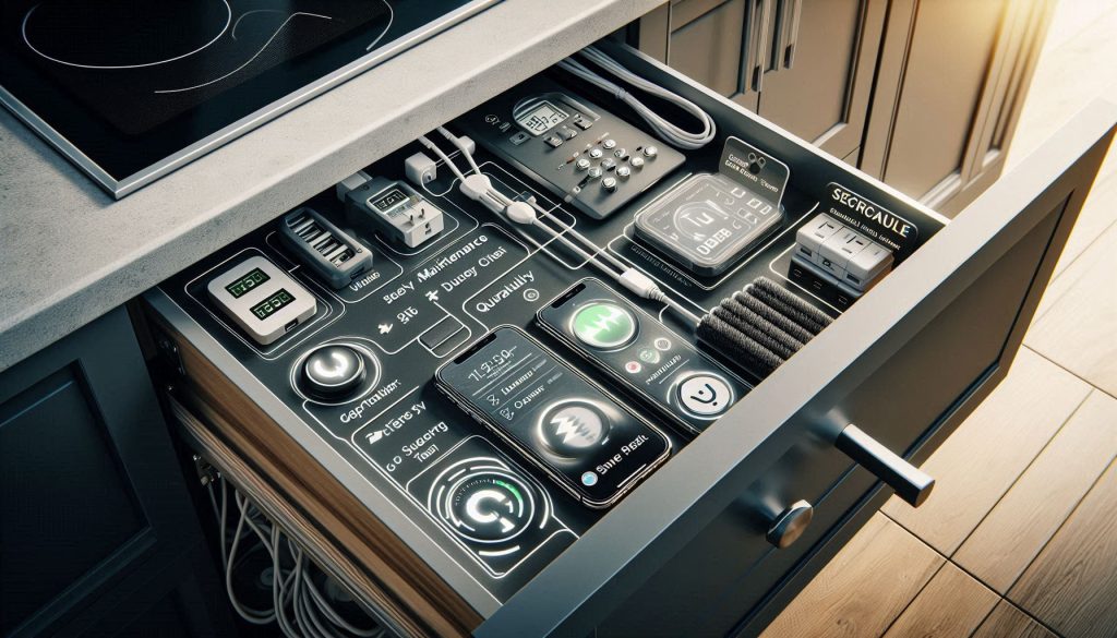
Maintenance schedule (what to do and when)
Weekly: quick visual sweep for frayed cables, loose connectors, dust build-up, or blocked vents.
Monthly: during normal peak use, touch-test port and hub surfaces for abnormal heat; measure a suspicious port with a USB power meter (Plugable USB-C Power Meter or ChargerLAB Power-Z).
Quarterly: press the GFCI test/reset button and verify the surge protector’s status LED; run a receptacle tester or multimeter to confirm outlet health.
After events: replace surge modules according to manufacturer guidance or immediately after a heavy lightning/utility event that trips the protector; if in doubt, swap the module.
Lifecycle: expect consumer PD modules to last ~3–5 years under heavy continuous use, 5–10 years with moderate duty; plan replacements on that cadence.
Troubleshooting flow (stepwise actions for common faults)
No power to the station
Check upstream outlet and breaker; reset GFCI; test outlet with a known‑good lamp.
Swap the power strip or surge protector with a known good unit to isolate the fault.
A single port or outlet not charging
Swap cables and the device to another port. If the problem follows the port, replace the hub or module (e.g., swap an Anker PowerPort Atom PD 4).
Use a USB power meter to measure voltage/current under load.
Intermittent wireless charging
Ensure the phone’s case isn’t thicker than spec; realign the coil and remove metallic mounts.
Test with another Qi pad model (e.g., Nillkin or Belkin Boost↑Charge) to isolate pad vs. phone.
Devices throttling or shutting down from heat
Measure surface temps during peak use; add ventilation or a quiet fan (Noctua) if temps exceed manufacturer thresholds.
Temporarily reduce simultaneous loads; if performance returns, add headroom before scaling.
Scaling and security (planning for more devices)
Headroom: keep at least 25–30% spare power capacity above your measured peak load.
Prefer modular PD hubs (Anker, Satechi) so you can add a second unit without rewiring.
Document wiring, breaker loads, and load calculations before expanding; photograph connections.
Smart chargers: keep firmware updated, change default passwords, and isolate them on a guest or IoT VLAN to reduce network risk.
End-of-life and disposal
Recycle failed electronics via Call2Recycle or local e‑waste programs; remove batteries where required.
Destroy or render unusable damaged power modules and follow manufacturer RMA for hazardous failures.
With these routines and checks you’ll keep the station safe, efficient, and ready for additional devices as your household changes—now move on to tying everything together in the Conclusion.
Bringing It Together: A Safe, Functional, and Low-Visibility Charging Solution
You now have a comprehensive plan: assess device needs and power, choose certified hardware and enclosures, follow stepwise installation and testing, and apply safety and maintenance practices. The most critical actions are accurate load calculation to avoid circuit overloads, selecting UL/ETL‑listed components and tamper‑resistant outlets, ensuring adequate ventilation and heat dissipation for chargers and batteries, and engaging a licensed electrician whenever you alter household wiring or approach the panel. Follow manufacturer specs, label circuits, and include GFCI/AFCI protection where code requires it.
Take these steps and your hidden kitchen counter charging station will be convenient, durable, low‑visibility, and—above all—safe for everyday use. Start planning now and consult professionals as needed.